Ship completeness coefficient formula. The geometry of the hull and the buoyancy of the vessel. Theoretical drawing. The main dimensions of the vessel and their ratios, coefficients of completeness. Taking a ship aground by moving the ship's center of gravity
The calculation of the displacement is carried out using the equation of masses of the following form:
D- the required displacement of the vessel.

 - a measuring device for the mass of the case equipped;
 - meter of mass of displacement stock;
 - the speed of the vessel in full load in calm, deep water;
 - admiralty coefficient;
 - measuring device mass of mechanisms (power plant);
 - coefficient taking into account additional fuel, oil, feed water;
 - coefficient of marine safety;
 - specific fuel consumption;
 - autonomy; hour.
 - carrying capacity;
 - the mass of the crew;
Dw – deadweight;
 - mass of variable liquid cargo.
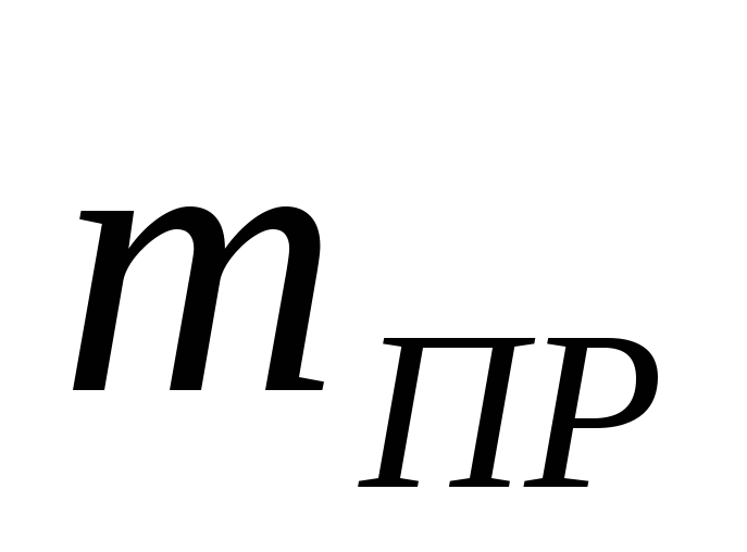
The weight meter of the equipped case is calculated according to the prototype: project 17310.
 ,
,
 .
.
Density of sea water - 
 ;
;
Estimated length, L- 93.5 m;
Width, B- 13.4 m;
Draft, T- 4.6 m;
The mass of the hull of the equipped prototype is equal to:  T.
T.
 .
.
The gauge of the mass of the displacement stock at this stage of design is taken to be in the range from 0.01 to 0.025. We will accept  .
.
Let's calculate the coefficient A from the mass equation:
Coefficient V:

Admiralty coefficient Ca calculated by the prototype by the formula:

Prototype speed  = 11 knots. Prototype speed data are given at draft T= 4.6 m.
Main motor power is Ne= 1740 kW.

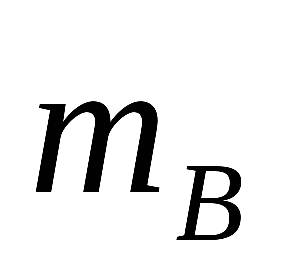
The mechanism mass meter is equal (the prototype mechanism mass is  T)
T)

Coefficients of additional fuel and marine reserve are assumed to be equal:

Specific fuel consumption is:

Vessel autonomy in hours t is equal to:

Mass Equation Coefficient B is equal to:
The mass of the crew and supplies is equal to:
 - the mass of the crew;
 - weight of provisions;
 - the mass of fresh water;
 - the mass of food and solid waste.
Crew weight: t.
 - the number of crew members,
Provision stock mass: t.
A- autonomy (day), A=15
Fresh water mass: t.
Mass of food and solid waste: t.
The mass of sewage and drainage waters is equal to:
Mass Equation Coefficient WITH is equal to:
The mass equation of the projected vessel is presented in the form:
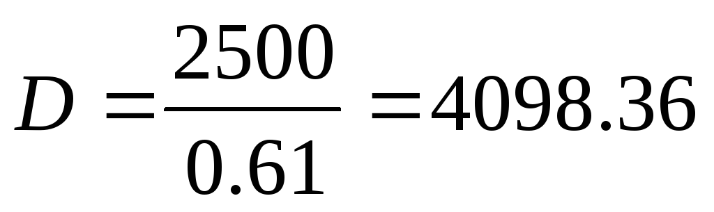
We find the solution to the equation iteratively using the formula:

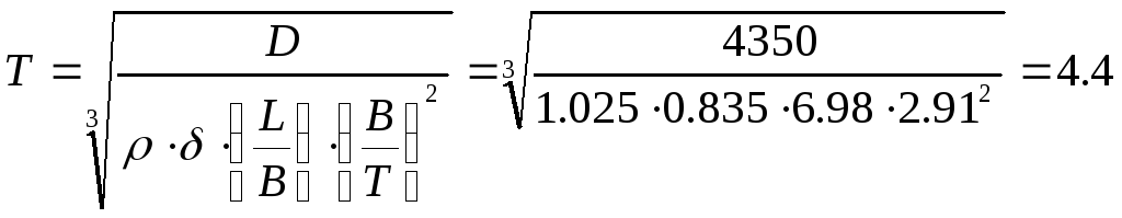
D= 4350 t.
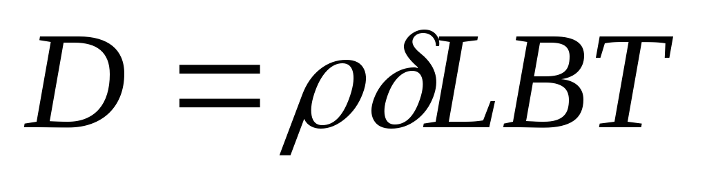
As a control of the found displacement, we check the displacement by utilization factors.


 T.
T.
The difference in determining the displacement in two ways is 5%.
For further calculations, the displacement is taken D = 4350 t.
2.2 Determination of main dimensions in the first approximation
The main dimensions in the first approximation are calculated using the buoyancy equation
 , where

 - the density of sea water;
 - coefficient of displacement completeness;
L, B, T- length, breadth and draft of the vessel at design waterline
To solve this equation, you need to set additional parameters:  , which in the first approximation we take the same as in the prototype.


Then the draft of the vessel is determined by the formula:
 m.
m.
The width of the vessel is equal to: 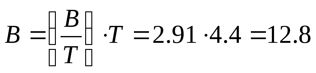 m
m
The length of the vessel is equal to:  m
m
The depth of the projected vessel is calculated by the formula: 

The ratio of the main dimensions of the vessel, if possible for the I limited navigation area, should not go beyond:
 ;
;


We will control the coefficient of the fullness of the displacement according to the speed mode of the vessel.

The displacement completeness factor for dry cargo ships should be within the range 
Since the coefficient of displacement completeness fits into the recommended range, then for further design we take δ= 0.835
For further calculations, the width of the vessel is assumed to be: B = 12.8 m.
Taking into account the rounding off, the length of the projected vessel is taken equal to:

 m.
m.
Actual freeboard of the vessel, m.
The minimum possible freeboard is 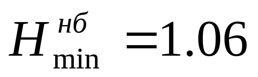 m.
m.
The depth complies with the load line rules in terms of freeboard.
The main, or main, geometrical dimensions of the vessel are length L, width B, depth H, freeboard F, draft T and overall height of the vessel with superstructures h, (Figure 5). The ratio of these dimensions characterizes the shape of the vessel and its main qualities.

Figure 5 - Theoretical and overall dimensions of the vessel
There are the following main dimensions:
a) theoretical (calculated), measured according to the theoretical drawing without taking into account the thickness of the outer shell of the hull;
b) practical (constructive), measured taking into account the thickness of the skin;
c) overall (largest), measured between the extreme non-removable protruding parts of the vessel.
The length of the vessel L is measured in DP between the perpendiculars along the GVL, and in the presence of a cruising stern, between the forward and stern perpendiculars, drawn along the axis of rotation of the rudder. Distinguish the greatest length of the vessel L max as the greatest distance in the center plane. Breadth B is measured at the cargo waterline at its widest point. Overall width B max is measured in the midship plane between fixed parts (including fenders).
The ship's draft, T, is measured amidships as the distance from the base plane to the cargo waterline. If the vessel is trimmed, then the draft T cf is measured as the half-sum of the draft in the bow T H and in the stern T K
The draft in the bow T N and in the stern T k, in turn, is measured from both sides of the vessel and calculated by the dependencies
Maximum draft T max. there is an overall dimension along the perpendicular from the GVL to the protruding outer edges of the bottom skin or protruding parts of the rudder, propeller or their enclosures.
Depth H is the vertical distance from the base plane to the topside line, measured in the midship plane. Freeboard F is the distance from the GVL to the topside line in the midship plane. The height of the vessel h is the overall dimension from the GVL to the highest point of the vessel. You need to know this size when passing ships under bridges. To characterize the shape of the ship and some of its qualities, the relationship of the above dimensions of the ship to each other is of great importance.
The L / B ratio affects the speed of the boat. The larger it is, the sharper the vessel, the less resistance to movement. Most often, this ratio is within 48.
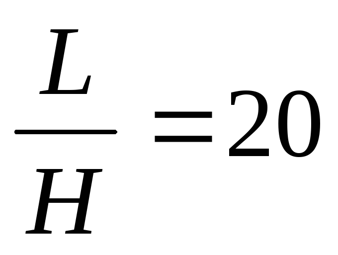
The L / H ratio affects the strength of the vessel. The larger it is, the more weight additional materials are needed to ensure the desired strength of the vessel. For tugboats this ratio is within 812, for cargo ships it reaches 50.
The B / L ratio affects the stability of the vessel. With its increase, the initial stability increases.
The B / T ratio affects stability, propulsion and course stability. The more W / T, the more stable the ship; for tugboats B / T = 2 4, for cargo ships up to 12.
The L / T ratio affects the turnability of the boat; the smaller it is, the more maneuverable the vessel is (excluding water jet vessels, where the turnability is ensured by the release of water through special side nozzles).
The H / T ratio affects the stability, strength and tonnage of a vessel. For motorboats, it ranges from 1.2 to 3.6; for cargo ships - from 1.05 to 1.6.
For a better understanding of the ship's forms, dimensionless completeness coefficients are also used, obtained from comparing the areas and volumes characteristic of the ship with the correct simplest geometric areas and volumes. Completeness coefficients are used at the initial design stage, as well as when solving many practical issues for quick and approximate identification of some of the main elements of the vessel. To obtain these coefficients, it is customary to designate the GVL area through S (it characterizes the completeness of the ship's contours in the plan - in horizontal section); midship area through and (it characterizes the completeness of the ship's contours in cross section); the area of diameter through A (it characterizes the completeness of the ship's contours in the longitudinal section); the volume of the underwater part of the vessel through V, which is the volumetric displacement, which characterizes the total completeness of the vessel's contours.
The ratios of the named areas and volumes to the areas and volumes of geometrically correct figures with the same overall dimensions are called the completeness coefficients of the underwater part of the vessel.
The coefficient of completeness of GVL b is the ratio of the area of the cargo waterline S to the area of a rectangle with sides L and B, i.e.
navigational vessel buoyancy cargo capacity
Its values for river cargo ships range from 0.84 to 0.9.
The coefficient of completeness midship is the ratio of the area of the midship frame to the area of a rectangle with sides B and T, i.e.
Its value for river cargo ships is 0.96? 0.99.
The coefficient of completeness of the diameter r is the ratio of the area of the diameter A to the area of a rectangle with sides L and T, i.e.
This coefficient is rarely found in calculation practice.
The coefficient of the completeness of the volumetric displacement d is the ratio of the volume of the vessel V to the volume of the parallelepiped with sides L, B and T, i.e.
Its values fluctuate within 0.85? 0.90.
The coefficient of the longitudinal completeness of the displacement q is the ratio of the volumetric displacement of the vessel V to the volume of the prism with the base equal to the area of the midsection and and the height L, i.e.
The coefficient of vertical displacement h is the ratio of the volumetric displacement V to the volume of the prism with the base equal to the area of the cargo waterline S and the height T, i.e.
The coefficient of lateral displacement w is the ratio of the volumetric displacement of the vessel V to the volume of the prism with the base equal to the area of diameter A and height B, i.e.
This coefficient is almost never found in calculation practice.
Thus, the completeness coefficients b, c, d and e are basic, and c, h and w are derivatives.
Completeness factor
The shape of the underwater part of the ship's hull is characterized by the completeness coefficients.
The coefficient of completeness of the cargo waterline (GVL) is the ratio of the area of the cargo waterline to the area of the circumscribed rectangle:
where S is the area of the waterline
The coefficient of completeness of the midship frame in is the ratio of the submerged area of the midship of the frame (A) to the area of the circumscribed rectangle:
The general completeness coefficient d is the ratio of the volume of the underwater part of the vessel V to the volume of the described parallelepiped:
The coefficient of vertical completeness h is the ratio of the volume of the underwater part of the vessel to the volume of the cylinder, the base area of which is equal to the area of the waterline (S), and the height is the draft of the vessel (T):
The coefficient of longitudinal completeness q is the ratio of the volume of the underwater part of the vessel to the volume of the cylinder, the base area of which is equal to the area of the midship frame (A), and the height is the length of the vessel (L):
Theoretical drawing
The shape of the ship is most fully determined by the theoretical drawing of the ship - a set of projections of sections of the surface of the ship on the three main mutually perpendicular planes of the ship.
The main planes of the projections of the theoretical drawing are taken as the diametrical plane, the main plane and the plane of the mid-frame.
The lines of intersection of the ship's surface by planes parallel to the centerline are called buttocks. The lines of intersection of the surface of the ship by planes parallel to the main plane are called waterlines, and the lines of intersection of the surface of the ship by planes parallel to the plane of the midship frame are called theoretical frames.
The projection of all these lines onto the diametrical (vertical) plane is called “BOK”. Buttocks in this projection are displayed without distortion, and waterlines and frames are visible in the form of straight lines. The projection of the intersection lines onto the horizontal (main) plane is called “HALF”. Waterlines on this projection are displayed without distortion, and buttocks and frames are shown as straight lines. Since the waterlines are symmetrical (with the symmetrical shape of the vessel), they are displayed at half-latitude only on one side of the DP. At half-latitude, the line of intersection of the deck and side is also depicted. The projection of all lines of intersection on the plane of the midship frame is called "BODY" (profile projection). On the hull on the right side of the DP depict the projection of the bow frames, and on the left side - the stern frames. Waterline and buttock projections are drawn as straight lines
A theoretical drawing is necessary for calculating seaworthiness - buoyancy, stability, unsinkability, construction of the ship's hull, as well as in operation - to determine the size of the premises and the distance to the holes in the ship's hull.
Stability and metacentric height. The ship, the yacht are subject to the action of forces and moments of forces tending to tilt them in the transverse and longitudinal directions. The ability of a vessel to resist these forces and return to a straight position after they cease to be applied is called stability. The most important thing for a yacht is lateral stability.
When the ship is floating without heel, then the forces of gravity and buoyancy, applied respectively in the CG and CV, act along the same vertical. If during a roll, the crew or other components of the mass load do not move, then for any deviation of the CG, it retains its original position in the DP, point G in the figure, rotating with the ship.
At the same time, due to the changed shape of the underwater part of the hull, the CV is shifted from point C towards the inclined side to position C1. Due to this, a moment of the pair of forces D and gV arises with the shoulder l equal to the horizontal distance between the CG and the new CV of the yacht. This moment seeks to return the yacht to a straight position and is therefore called restoring.
When rolling, the CV moves along the curve of the trajectory C0C1, the radius of curvature r of which is called the transverse metacentric radius, r the center of curvature M corresponding to it is called the transverse metacentre. The value of the radius r and, accordingly, the shape of the C0C1 curve depends on the hull contours. V general case as the bank increases, the metacentric radius decreases, since its value is proportional to the fourth power of the waterline width.
Obviously, the shoulder of the restoring moment depends on the distance - the elevation of the metacentre above the center of gravity: the smaller it is, the less shoulder l is, respectively, during roll. At a very early stage, the slope of GM or h is considered by shipbuilders as a measure of the stability of a ship and is called the initial transverse metacentric height. The larger h, the more heeling force is needed to tilt the yacht to a certain heel angle, the more stable the vessel. On cruising-racing yachts, the metacentric height is usually 0.75-1.2 m; on cruising dinghies-0.6-0.8 m.
It is easy to establish from the GMN triangle what the restoring shoulder is.

The restoring moment, taking into account the equality of gV and D, is equal to:
 Thus, despite the fact that the metacentric height varies within rather narrow limits for yachts of different sizes, the amount of restoring moment is directly proportional to the displacement of the yacht, therefore, a heavier vessel is able to withstand a heeling moment of a greater magnitude.
The restorative shoulder can be thought of as the difference between two distances:
lf - shoulder of stability of shape and lw-shoulder of stability of weight. It is not difficult to establish the physical meaning of these values, since lw is determined by the deviation of the line of action of the weight force from the initial position during roll from the initial position exactly above C0, and lw is determined by the shift to the leeward side of the center of the immersed volume of the hull. Considering the action of the forces D and gV relative to Co, it can be seen that the force of the weight D tends to heel the yacht even more, and the force gV, on the contrary, straightens the ship.
According to the triangle CoGK, you can find that, where CoC is the elevation of the CG above the CB in the straight position of the yacht. Thus, in order to reduce the negative effect of weight forces, it is necessary to lower the CG of the yacht as much as possible. Ideally, the CG should be located below the CV, then the stability shoulder becomes positive and the yacht's mass helps her resist the heeling moment.
However, only a few yachts have such a characteristic: the deepening of the CG below the CW is associated with the use of very heavy ballast, exceeding 60% of the yacht's displacement, excessive lightweight structure of the hull, spars and rigging. The effect is similar to the decrease in CG, given by the movement of the crew to the windward side. If we are talking about a light dinghy, the crew manages to shift the overall CG so much that the line of action of the force D intersects with the DP well below the CV and the weight stability arm turns out to be positive.
In a keel yacht, due to the heavy ballast false keel, the center of gravity is quite low (most often under the waterline or slightly above it). The stability of the yacht is always positive and reaches its maximum at about 90 ° heel when the yacht is sailing on the water. Of course, such a heel can only be achieved on a yacht with securely sealed openings in the deck and a self-draining cockpit. A yacht with an open cockpit can be flooded with water at a much lower bank angle (a yacht of the Dragon class, for example, at 52 °) and go to the bottom without having time to straighten.
In seaworthy yachts, a position of unstable balance occurs at a heel of about 130 °, when the mast is already under water, being directed downward at an angle of 40 ° to the surface. With a further increase in the roll, the stability shoulder becomes negative, the overturning moment contributes to the achievement of the second position of unstable balance at a roll of 180 ° (up keel), when the CG is located high above the CV of a sufficiently small wave for the vessel to return to the normal downward keel position. There are many known cases when yachts made a full 360 ° revolution and retained their seaworthiness.
Fighters on frames and waterlines. To characterize the distribution of displacement forces along the length of the vessel, a special plot is built, called the drill on the frames. To construct this diagram, the horizontal line, expressed in the accepted scale, the theoretical length of the vessel, is divided into n equal parts equal to the number of spacing on the theoretical drawing of the vessel.

On the perpendiculars restored at the points of division, the values of the areas of the submerged parts of the corresponding frames are laid on a certain scale and the ends of these segments are connected by a smooth line. The combatant area along the frames is equal to the displacement volume of the vessel.
In the absence of a theoretical drawing, the volumetric displacement of the vessel can be approximately determined by its main dimensions:
V = k * L * B * T,
where L, B, T - respectively the length, breadth and draft of the vessel; k - coefficient of displacement completeness or overall ratio completeness. The values of the coefficient of completeness k for various types of ships are taken according to reference data.

Militant on frames.
Since the center of the ship's size is located in the center of gravity of the underwater part of the ship, and the combatant area expresses the volume of the underwater part, the abscissa of the center of gravity of the combatant along the frames is equal to the abscissa of the center of the ship's size.
A similar diagram, characterizing the distribution of displacement forces along the height of the vessel, is called the drill along the waterline.

Militant along the waterlines.
The combatant area along the waterlines is also equal to the volumetric displacement of the vessel, and the ordinate of its center of gravity determines the position of the center of the vessel's size along its height.
If we take into account the properties of the combatants along the frames and waterlines, then determining the location of the center of the vessel's size will be reduced to calculating the abscissa of the center of gravity of the combatant along the frames and the ordinate of the center of gravity of the combatant along the waterlines.
Calculation of the area of the submerged part of the frame using the trapezoid method. To calculate the roll and trim, it is necessary, in addition to the mass and position of the ship's CG, to know its volumetric displacement and the position of the center of magnitude, CV, which is the center of gravity of the volume of water displaced by the ship's hull. The simplest way to calculate these values is to plot combatant on frames.

The DP line at the half-latitude of the theoretical drawing serves as a base for the construction of this curve, while the lines of the theoretical frames are extended downward. On each of these lines, on a certain scale, the submerged area of the corresponding spargout should be set aside. For sharp-cheekbones, flat-bottomed or dead-sea vessels, it is not difficult to calculate the area of a schnaigout: it is enough to divide it into simple geometric shapes - rectangles, triangles, trapezoids.

The same principle can be applied to calculate the areas of frames of round bilge hulls, but a more accurate result gives trapezoidal method... Its essence is as follows. If the figure, bounded by a curved line, is divided by equally spaced straight lines into a sufficiently large number of equal parts, then the area of each part can be calculated as for a trapezoid:

Summing then the areas of all trapezoids, you can get the area of the entire figure as the sum of the areas of all trapezoids:
Thus, to calculate the area of the frame, it is necessary to find the sum of all the ordinates yi along the waterlines minus the half-sum of the ordinates of the extreme waterlines - at OP and CWL, and multiply the result by the distance DT between the waterlines and by 2, since the calculation was carried out for half of the frame. A similar principle can be used to calculate the area of any waterline, which is divided by theoretical frames into segments DL of equal length.
Having found the submerged areas of each frame Wi on the projection of the hull, they are laid down from the DP in a certain scale, then a smooth curve is drawn. It is easy to figure out what if, for example, the ordinates of the areas shp. 5 and 6 and multiply by the distance between the frames DI, you get the volume of the part of the hull as a truncated pyramid, having bases in the form of parts of shp 5 and 6 immersed in water.
All quantities here must be expressed in m and m2. Using the trapezoidal rule, it is possible to find the position of the center of magnitude - CV, since it must coincide with the position of the center of gravity of the combatant along the waterline relative to the midsection. For this, the static moment of the area, limited by the combatant along the frames, is calculated relative to the mid-section - the frame, and the abscissas of the bow frames are taken with a plus sign, aft ones - with a minus sign. With ten theoretical frames:
The abscissa CV from the midsection is:

Calculations to determine the coordinates of the ship's center of gravity... Calculations to determine coordinates the center of gravity of the vessel it is convenient to keep it in a tabular form, which is called a weight log. This log records the weights of all the elements of the vessel itself and all the cargo on it.
If we take into account the properties of the combatants along the frames and waterlines, then determining the location of the center of the vessel's size will be reduced to calculating the abscissa of the center of gravity of the combatant along the frames and the ordinate of the center of gravity of the combatant along the waterlines.
Using the definition known from statics for the static moment of the area, you can write formulas for determining the coordinates of the center of the vessel's magnitude:

where wi and wi * - areas of combatant units, enclosed between two adjacent frames or waterlines; Xi, Yi, Zi - coordinates of the centers of gravity of the corresponding areas.
At tentative calculations you can use approximate formulas to determine the location of the center of gravity, center of magnitude and metacentre for the height of the vessel.
The ordinate of the ship's center of gravity is determined by the expression:

where:
k is a practical coefficient, the value of which, for example, for boats lies in the range of 0.68 - 0.73
h is the height of the side of the vessel.
Center of magnitude ordinates. To calculate the ordinate of the center of magnitude, the formula of Academician V.L. Pozdyunin is recommended:

Zс = T / (1-b / a).
where T is the sediment
b (betta) - coefficient of full displacement
a (alpha) coefficient of completeness of the cargo waterline.
Static stability diagram. Static stability diagram It is obvious that the complete characteristic of the stability of a yacht can be the curve of the change in the restoring moment MB depending on the heel angle or the static stability diagram. The diagram clearly shows the moments of maximum stability (W) and the limiting heel angle at which the ship, being left to itself, capsizes (3-angle of sunset of the static stability diagram). or other windage with a wind of a certain strength. To do this, the curves of the heeling moment Mcr are plotted on the stability diagram depending on the roll angle. Point B of intersection of both curves indicates the heel angle that the yacht will receive under static, smoothly increasing wind action. In the figure, the yacht will get a roll corresponding to point D - about 29 °. For vessels with pronounced descending branches of the stability diagram (dinghies, compromises and catamarans), sailing can only be allowed when heel angles do not exceed the maximum point on the stability diagram.

Comparison of the outlines of different vessels. When comparing the outlines of various vessels and performing calculations of their seaworthiness, dimensionless coefficients of completeness, volumes and areas are often used. These include:
— displacement completeness ratio or overall completeness — δ linking the linear dimensions of the body with its immersed volume. This coefficient is defined as the ratio of the volumetric displacement V by design waterline to the volume of a parallelepiped with sides equal to L, B and T;

The smaller the coefficient , the sharper the contours of the vessel and, on the other hand, the less the useful volume of the hull below the waterline;
- coefficient of completeness of the waterline area - α and - β midship - frame; the first is the ratio of the area of the waterline S to the rectangle with sides L and B;

Waterline completeness coefficients can be calculated using the approximate formula:
 We accept
Coefficient of completeness midship - frame:
 We accept
4.8 Determination of maximum cargo capacity
Specific cargo capacity µ can be determined from the cargo capacity equation, provided that the ratio  , where
  - specific loading volume.
 , where
  - coefficient taking into account walkways, ladders, other places not occupied by cargo;
 - coefficient of hold completeness;
 - coefficient taking into account the volume occupied by the set, double bottom and double sides in the hold area;

 - the ratio of the length of the holds to the length of the vessel.
Then the definition of specific cargo capacity
4.9 Analysis of the obtained results.
Based on approximate calculations, we have the following main characteristics:


5 General arrangement sketch development. Determination of the center of gravity of the vessel... Udifferentska
We will begin the development of the general arrangement by dividing the case into compartments. The practical space can be chosen:
The rules allow a deviation from this value within 

In the forepeak and afterpeak, the spacing should be no more than 600 mm, therefore it is advisable to take a spacing of 0.6 m along the entire length of the vessel. The forepeak bulkhead must be impervious to the freeboard deck and extend at least 5% of the ship's length and not more than 3 + 0.05L
 , where
  - forepeak length
We accept  = 6.6 m or 11 spacing.
The aft-peak bulkhead shall be impervious to the freeboard deck and the distance from the bulkhead to the perpendicular shall be selected taking into account the design of the aft end. This distance takes 11 spacing or 7.2m.
We install a transverse bulkhead from the forepeak to the stern, separating the device and the service room. The length of this compartment is 5 spans or 3 m.
We place the engine room and the residential superstructure in the stern, like in the prototype. The rest of the hull is reserved for cargo holds. The length of the engine room is 32 frames or 19.2 m. In the area of cargo spaces, the sides are double and we install two transverse bulkheads dividing the cargo space into three holds, 30 frames or 30 m long each. The total number of transverse bulkheads on the ship is 6, which meets the requirements of the Register. The double bottom extends from the forepeak bulkhead to the afterpeak bulkhead.
According to the adopted general arrangement scheme, we draw a sketch in Figure 5.1. Using the sketch of the general position and mass load, we determine the position of the center of gravity of the vessel along the length and height. The calculation is carried out according to table 5.1.
T  Table 5.1 - Calculation of the ship's center of gravity
|
Name | ||||||
|
Equipped body | ||||||
|
Mechanisms | ||||||
|
Displacement reserve | ||||||
|
Empty displacement | ||||||
|
Crew, provisions, water | ||||||
|
Cargo transported | ||||||
|
Fuel, oil | ||||||
|
Variable liquid cargo | ||||||
|
Full load displacement | ||||||
After that, you can proceed to trimming the ship in full load, so that the ship in full load sits on an even keel, then its center of gravity should be on the same vertical with the center of magnitude, i.e.  .
.
The center of magnitude is determined by the approximate formula:

Thus, we accept 
It might be helpful to read:
- Determination of voids in the ground How to search for voids in the ground with a sound blow;
- "Ksenia Sobchak put forward her candidacy for the presidency and said that those who are" against all;
- "An insignificant deal": Sobchak's speech in court in the "Putin case" was made public (video) Cannibals and puppets;
- Sobchak's election speech;
- "center for continuing education";
- The most ambitious aircraft carriers in the world;
- How many aircraft carriers does the UK have for a year;
- “I hate introspection Makarevich interview;