Practical work on using idef0 for functional description of CAD software. IDEF0. Familiarity with notation and example of use Simple examples of construction in idef0
Did you know,
what is a thought experiment, a gedanken experiment?
This is a non-existent practice, an otherworldly experience, the imagination of what is not in reality. Thought experiments are like waking dreams. They give birth to monsters. Unlike a physical experiment, which is an experimental test of hypotheses, a "thought experiment" trickeryly replaces experimental verification with desired, untested in practice conclusions, manipulating logical constructions that actually violate logic itself by using unproved premises as proven ones, that is, by substitution. Thus, the main task of applicants for "thought experiments" is to deceive the listener or reader by replacing a real physical experiment with his "doll" - fictitious reasoning on parole without physical verification itself.
Filling physics with imaginary, "thought experiments" led to the emergence of an absurd surreal, confused and confused picture of the world. A true researcher must distinguish such "candy wrappers" from real values.
Relativists and positivists argue that the "thought experiment" is a very useful tool for testing theories (also appearing in our minds) for consistency. In this they deceive people, since any verification can only be carried out by a source independent of the object of verification. The applicant of the hypothesis himself cannot be a test of his own statement, since the reason for this statement itself is the absence of contradictions in the statement visible to the applicant.
We see this on the example of SRT and GRT, which have turned into a kind of religion that governs science and public opinion. No amount of facts that contradict them can overcome Einstein's formula: "If a fact does not correspond to the theory, change the fact" (In another version, "- The fact does not correspond to the theory? - So much the worse for the fact").
The maximum that a "thought experiment" can claim is only the internal consistency of the hypothesis within the framework of the applicant's own, often by no means true, logic. This does not test the suitability of practice. This test can only take place in a valid physical experiment.
An experiment is an experiment in that it is not a refinement of thought, but a test of thought. A thought that is self-consistent within itself cannot verify itself. This is proven by Kurt Gödel.
Ministry of Education and Science of the Russian Federation
Federal Agency for Education
State educational institution higher professional education
Course work
"System Modeling"
"Development of a greenhouse enterprise model using design methodologies IDEF0, DFD and IDEF3"
1. Purpose of work
2. Theoretical introduction
3. Description of the subject area
4. Description of BPwin
4.1 The principle of construction of the IDEF0 model
4.2 Principle of building a DFD model
4.3 The principle of construction of the IDEF3 model
5. Simulation
5.1 Greenhouse model
5.2 Mathematical model
6. Comparative analysis
6.1 Methodologies
6.2 Comparison of tools
Literature
1. Purpose of work
The objectives of this course work were:
application of methods of pre-project survey of the enterprise;
analysis of the materials obtained for subsequent modeling;
development of a process model in the IDEF0 standard;
description of workflow and information processing in the DFD standard;
descriptions of processes in the IDEF3 standard;
development of a mixed process description model based on IDEFO, DFD and IDEF3 standards.
creation of scenarios for the enterprise;
building structural diagram enterprises;
creation of a mathematical model of this enterprise.
comparative analysis
2. Theoretical introduction
When developing automated systems control at the stages of coding and testing, a large number of errors are revealed, the correction of which entails a radical change in the entire system being developed. Such errors are taken into account when modeling and in-depth, detailed analysis of the projects being created. Modeling allows you to "see" the project in the development process and create prerequisites for analyzing the behavior of the system depending on the initial conditions.
For the correct coordination of the processes occurring in the simulated control system, it is necessary to create a structure, i.e. streamline processes. Simulation of work information system especially important in the early stages of its creation. Since correcting the mistakes made at this stage is the most expensive, the benefits at the stage of analyzing the problem and developing a logical model for its solution are significant.
In this regard, it is necessary to study and develop a subject area, namely the work of the greenhouse economy. To do this, you need to understand the terminology of this area, collect the necessary regulatory and legal documents, study samples of documents of a given enterprise and trace their movement both within the enterprise and outside it.
The next stage of development is the design stage. Before starting the design and implementation, you need to have an accurate and detailed understanding of the requirements at a high level. It is also very useful to have a requirements framework that can be used as input to shape the system. All this is achieved through analysis and modeling.
In the process of working at the stages of modeling and design, it is necessary to obtain a system design containing enough information for its implementation. It is also necessary to analyze the work of the greenhouse economy, as a result of which it is possible to judge the degree of workload of each department, what needs to be automated in the first place and by what means.
The main goals of modeling in the development of projects are:
presentation of the activities of the enterprise and the technologies adopted in it in the form of a hierarchy of diagrams that provide clarity and completeness of their display;
formation on the basis of the analysis of proposals for the reorganization of the organizational and management structure;
streamlining of information flows (including workflow) within the enterprise;
analysis of requirements and design of specifications for corporate information systems.
3. Description of the subject area
For consideration in this term paper the work of the greenhouse economy was taken as a basis. This company specializes in the cultivation of agricultural crops. The products are sold at the request of the customer.
The organization of work is carried out according to the following scheme:
This diagram shows the departments of the enterprise, their functions and interrelation. Some of the departments can be automated.
At the head of the entire enterprise is the management, represented by the chief and his deputy. Their main function is to control the activities of the enterprise.
Labor protection service, the main function of which is personnel training;
The accounting department deals with document circulation;
Production control service, carries out full control at all stages of production;
Sector Maintenance, is engaged in renovation work.
Departments, services and workplaces of this enterprise are presented in table 1:
table no. 1

The tasks and functions of our greenhouse economy are shown in table 2:
Table 2


The documentation is presented in tables # 3:
table number 3

The directory of organizations is presented in table No. 4:
table no. 4


The following is a diagram describing the scenario of the enterprise's work with the corresponding conclusions for each of the stages: the customer receives an application for the supply of certain products of the greenhouse economy to the sales manager. The sales manager processes this request and makes a decision. Parallel to this, the accountant calculates the cost of providing services. Once all these stages are passed, the contracting process begins. The sales manager discusses the terms of the contract with the customer and makes its conclusion. After that, the customer makes the payment. Control over payment is the responsibility of the accounting department. The accountant receives a statement from the bank, and forms an order to start the execution of the order, which is transferred to the technologist. The technologist, in turn, draws up a plan - a schedule of work carried out and keeps records of the necessary funds. After drawing up a plan - a work schedule, an order is given to the gardener to carry out land work. The gardener is doing land work and harvesting. The harvested crop is sent to the customer. In the course of everything production cycle the head of the enterprise receives reports on the activities of the sales manager, accountant and technologist. The chief controls the entire process of the enterprise, and, if necessary, makes comments on the work of his personnel in order to improve the production process and the work of the entire enterprise as a whole.

Enterprise scenario diagram
4. Description of BPwin
BPwin is a small integrated modeling tool that supports several types of models and methods.
To analyze and reorganize business processes, Logic Works offers a top-level CASE tool, BPwin, which supports IDEF0 ( functional model), IDEF3 (WorkFlow Diagram) and DFD (DataFlow Diagram). The main of the three methodologies is IDEF0. BPwin has a fairly simple and intuitive user interface that enables the analyst to create complex models with minimal effort.
BPwin automates the tasks associated with building development models by providing the semantic rigor necessary to ensure correct and consistent results. This is achieved by applying the following methodologies in BPwin: IDEF0, DFD, and IDEF3.
But before tackling this more complex task, it is really necessary at least to "recalculate" all the elements of the business, that is, to create the organizational structure of the company. The next step is to try to graphically depict the relationships between the various elements of the previously defined structure.
In BPwin, it is possible to build mixed models, that is, the model can contain both IDEFO diagrams and IDEF3 and DFD diagrams. A BPwin model is viewed as a collection of activities, each of which operates on a set of data. Work is depicted as rectangles, data as arrows.
All works of the model are numbered. The number consists of a prefix and a number. A prefix of any length can be used, but the prefix A is usually used. The context (root) work of the tree is numbered A0. The decomposition work A0 has numbers Al, A2, A3, etc. The lower-level decomposition jobs have a parent job number and a sequential sequence number, for example, A3 decomposition jobs will have numbers A3.1 A3.2, A3.Z, A3.4, etc.
As a result of supplementing diagrams, IDEFO diagrams with DFD and IDEF3 diagrams, a mixed model can be created that best describes all aspects of the enterprise. The hierarchy of mixed model work can be seen in the Model Explorer window. Works in IDEFO notation are shown in green, DFD - in blue.
BPwin, as well as local integrated systems, practically does not allow performing complex analysis of systems, which is more or less necessary for the creation of small, medium and large PMIS. With their help, you can develop local IS or small subsystems designed to automate individual business chains, that is, when there is no need for a comprehensive analysis of the enterprise. A typical area of application of small integrated tools is the solution of problems of the so-called “piecewise” enterprise automation.
4.1 The principle of building the IDEFO model
The basis of the IDEFO methodology is a graphical language for describing business processes. A model in IDEFO notation is a collection of hierarchically ordered and interconnected diagrams. Each diagram is a unit of system description and is located on a separate sheet.
The IDEFO model assumes the presence of a clearly formulated goal of a single subject of modeling and one point of view.
The model can contain four types of charts:
context diagram (each model can have only one context diagram);
decomposition diagrams;
node tree diagrams;
exposure-only diagrams (FEO).
The context diagram is the top of the diagram tree structure and represents the most general description of the system and its interaction with the external environment.
This process is called functional decomposition, and the diagrams that describe each fragment and the interaction of the fragments are called decomposition diagrams.
The notation and methodology of IDEF0 is based on the concept of a "block", that is, a rectangle that expresses some function of the business. As you know, a rectangle has four sides. In IDEF0, the roles (functional values) of all parties are different:
the upper side has the meaning of "control";
left - "entrance";
right - "exit";
bottom - "mechanism".
The second element of the methodology and notation is a "flow" (called an "interface arc" in the standard) - an element that describes data, informal control, or something else that "influences" a function represented by a block. Depending on which side of the block the flow is directed to, it is respectively called "input", "output", "control".
The pictorial element representing "flow" is an arrow.
Governance is what governs the activities of the bureau, in this developing model, these are the laws on the individual PU.
The "enter" arrows introduce the functions of the input data; in the context diagram, these are the employee's personal data.
Exit arrows - Output. In a context diagram, this is various information that is presented in Pension Fund RF.
The "mechanism" arrow is the data affecting the processes. In the diagram, these are personnel and PCs.
After decomposition of the context diagram, each large fragment of the system is decomposed into smaller ones, while each fragment is given a name, and so on, until reaching the right level details of the description.
After each decomposition session, examination sessions are held - subject area experts indicate the correspondence of real business processes to the created diagrams.
The found inconsistencies are corrected, and only after passing the examination without comments, you can proceed to the next decomposition session. This is how conformity is achieved.
All intersections in the diagram are numbered, each number has a J prefix. You can edit the intersection properties using the Definition Editor dialog.
4.2 Principle of building a DFD model
Data flow diagrams (DFDs) are the primary means of modeling the functional requirements of a system design. With their help, these requirements are broken down into functional components (processes) and presented as a network connected by data streams. The main purpose of such tools is to demonstrate how each process transforms its inputs into outputs, as well as to reveal the relationship between these processes.
Two different notations are traditionally used to depict DFD: Yodana (Yourdon) and Gane-Sarson (Gane-Sarson). Further, when constructing examples, Yodan's notation will be used, all exceptions will be preliminarily discussed.
This methodology (Gane / Sarson methodology) is based on the construction of a model of the analyzed IS - projected or actually existing. In accordance with the methodology, the system model is defined as a hierarchy of data flow diagrams (DFD or DFD), describing the asynchronous process of transforming information from its input into the system to its issuance to the user. Diagrams of the upper levels of the hierarchy (context diagrams) define the main processes or subsystems of the IS with external inputs and outputs. They are detailed using low-level diagrams. This decomposition continues, creating a multi-level hierarchy of diagrams, until such a level of decomposition is reached, at which the process becomes elementary and it is impossible to detail them further.
Sources of information (external entities) generate information flows (data flows) that carry information to subsystems or processes. These, in turn, transform information and generate new streams that transfer information to other processes or subsystems, data storage devices or external entities - information consumers. Thus, the main components of data flow diagrams are:
external entities;
systems / subsystems;
processes;
data storage devices;
data streams.
4.3 The principle of construction of the IDEF3 model
IDEF3 can also be used as a process creation method. IDEF3 complements IDEFO and contains everything you need to build models that can later be used for simulation analysis.
Each work in IDEF3 describes a scenario of a business process and can be a component of another work. Since the script describes the purpose and scope of the model, it is important that the works are named with a verbal noun denoting a process of action, or a phrase containing such a noun.
The point of view of the model should be documented. Usually this is the point of view of the person responsible for the work as a whole. It is also necessary to document the purpose of the model — the questions that the model is intended to answer.
Junction. The end of one job can serve as a signal for the start of several jobs, or one job may wait for the completion of several jobs to start. Crossroads are used to display the logic of arrow interactions during merging and forking, or to display multiple events that may or should be completed before starting the next job. The types of intersections are presented in the table:
Intersection types
| Designation | Name | Meaning in case of merging arrows (Fan-in Junction) | Sense in case branching arrows (Fan-out Junction) |
| ||& | Asynchronous AND | All upstream processes must be completed | All of the following processes must be running |
| ||&|| | Synchronous AND | All upstream processes completed at the same time | All of the following processes run at the same time |
| || O | Asynchronous OR | One or more upstream processes must be completed | One or more of the following processes must be running |
| || O || | Synchronous OR | One or more upstream processes ended at the same time | One or more of the following processes run at the same time |
| || X | Only one upstream process completed | Only one next process starts |
All intersections in the diagram are numbered, each number has a J prefix. You can edit the intersection properties using the Definition Editor dialog. Unlike IDEFO and DFD, IDEF3 arrows can merge and branch only through intersections.
Reference object. A reference object in IDEF3 expresses an idea, concept, or data that cannot be associated with an arrow, intersection, or work. To add a link object, use the | R | - (add a link object to the diagram - Referent) in the tool palette. The reference object is drawn as a rectangle, similar to the work rectangle. The name of the reference object is set in the Referent dialog (item of the Name Editor pop-up menu), as the name you can use the name of an arrow from other diagrams or the name of an entity from the data model. Reference objects must be linked to units of work or intersections with dashed lines. The official IDEF3 specification distinguishes between three styles of reference objects - unconditional, synchronous, and asynchronous. BPwin only supports unconditional reference objects. Synchronous and asynchronous reference objects used in object state transition diagrams are not supported.
5. Simulation
5.1 Greenhouse model
Model Explorer

Context diagram:

Decomposition diagram A0:

A1 decomposition diagram:

IDEF3 A11.1 diagram:

Data flow diagram A12:

Decomposition diagram A2:

IDEF3 A21.1 diagram:

Decomposition diagram A3:

Decomposition diagram A4:

Decomposition diagram A5:

Decomposition diagram A6:

A63 data flow diagram:

5.2 Mathematical model
For a more detailed description of the work of the greenhouse economy, it is necessary to draw up a mathematical model for the product of the enterprise's activity.
This mathematical model will describe the calculation of the unit price in different conditions.
e - the cost of a unit of goods, determined by the manufacturer, it includes all costs associated with the production of a unit of goods, the main part of this figure is the purchase price of seeds;
v - purchase price of seeds, this is the price at which the company purchased seeds from the supplier (section "purchase of seeds");
a - labor expense ( wage and other expenses within the enterprise);
g - fuels and lubricants (fuels and lubricants);
n - taxes (consumption part) are established by the state and have a fixed rate;
k - VAT, value added tax, also has a fixed rate;
r - retail price, this is the amount of money for which the manufacturer sells a unit of his goods on the market, as a rule, the retail price is determined by the cost price with a certain percentage of the margin;
s - the company's markup per unit of goods, as a rule, its quantity is determined by each entrepreneur individually, in this case it is 40% of the cost price, i.e. (e * 40) / 100
o - the wholesale price, this is the amount of money offered per unit of goods, when buying from 100 units, in this case, a 10% discount from the retail price is valid;
os - discount for bulk purchases (os Mathematical model for calculating the cost per unit of manufactured goods: Mathematical model for calculating the retail price per unit of manufactured goods: Mathematical model for calculating the wholesale price per unit of manufactured goods: o = v + a + g + n + k + s - os o = r - (r * 10) / 100 The calculation of the cost of products at the "Greenhouse" enterprise is carried out by the accounting department, which controls the document flow, takes into account the income and expenses of the enterprise, keeps accounting books, and issues certificates. Based on these formulas obtained in the mathematical model of the enterprise, the accountant can calculate the price of goods, both retail and wholesale. 6. Comparative analysis To model our enterprise, we used 5 methodologies: Dragon, UML, IDEF0, IDEF3, DFD. In our opinion, the best way to represent the model of our enterprise is the UML methodology, since it more clearly and accurately reflects the main aspects of the greenhouse operation. UML diagrams are relatively easy to read. For example, the Use Cases diagram that was used to design the Greenhouse Implementation System enables the customer, end-user and developer to jointly discuss the functionality and behavior of the system. "Class diagram" allows you to describe the structure of the system, it demonstrates the classes of the system, their attributes, methods and dependencies between the classes, which can reveal in detail the scenario and organization of the enterprise. The Dragon methodology also has a very clear structure, but does not have such broad capabilities for modeling various systems. Visio is the simplest and most affordable process modeling tool. This product has standard, familiar to all control panels in the style of MS Office and easily integrates with any applications of this package, which makes it easier for inexperienced users to work with it. However, timing or value analysis requires report development, making this product much more difficult to use. Typical reports are clearly not sufficient for analyzing business processes. Despite this, Visio is a common tool for describing business processes both in Russia and abroad. Visio supports IDEF and UML formats for describing business processes. Independent development of formats is also possible. BPWIN - takes an intermediate place, distinguished by sufficient simplicity and great analysis capabilities. BPWIN's functionality is not only about drawing diagrams, but also checking the integrity and consistency of the model. BPWIN provides logical clarity in defining and describing diagram elements, as well as checking the integrity of the relationships between diagrams. The tool provides correction for the most common errors in modeling. In addition, BPWIN supports custom properties that are applied to chart elements to describe the specific properties of that element. The main limitation of this system is the underlying IDEF standard, in which there are severe limitations in the construction of models. This simplifies the task of describing simple procedures, but complicates the description of large processes. When describing complex processes, 1DEF diagrams begin to represent an innumerable set of interconnected diagrams that are outwardly very similar, which makes it difficult to understand the process as a whole. 7. Conclusion: In the course of this course work, all our goals were achieved. In this regard, we studied the subject area being developed, namely the work of the greenhouse economy. To do this, it was necessary to understand the terminology of this area, collect the necessary regulatory and legal documents, study samples of documents from our enterprise and track their movement both within the enterprise and outside it. From these activities, information was obtained from which an initial analysis was carried out and a design model was sketched. The next stage of development is the design stage. Before starting the design and implementation, you need to have an accurate and detailed understanding of the requirements at a high level. It is also very useful to have a requirements framework that can be used as input to shape the system. All this is achieved through analysis and modeling. By performing analysis and modeling, we achieved the separation of tasks that we prepared and simplified in the pre-design state for subsequent design and implementation activities. We distinguish between the problems that must be solved and the decisions that must be made in order to cope with them. As a result of work at the stages of modeling and design, we received a system design containing enough information for its implementation. After analyzing the work of the greenhouse economy, we can judge the degree of workload of each department, what needs to be automated in the first place and by what means. To facilitate the work, you can introduce new technologies that will facilitate the work in our farm. Literature: Rogozov Yu.I., Stukotiy L.N., Sviridov A.S. "Modeling of systems" TRTU, 2004. S.V. Maklakov “CASE-tools for the development of information systems. BPwin and Erwin ”–M .: DialogueMifi, 2001. Maklakov S. “Combining the structural and object approach in the new generation of Computer Associates CASE-tools” // Training and Consulting Center. 2002.
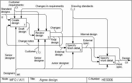
IDEF0 diagrams are built using the BPWin program. They are intended for graphical modeling of ongoing business processes.
About IDEF0 methodology
The IDEF0 methodology is widely used due to its simple and easy-to-understand graphical notation, which is very convenient for building a model. The main place in the methodology is given to diagrams. The diagrams display the functions of the system by means of geometric rectangles, as well as the existing connections between functions and the external environment. Links are shown using arrows. You can verify this by seeing what the IDEF0 diagram offers, examples of which can be found in this article.
The fact that only two graphic primitives are used in modeling allows you to quickly explain the current rules of IDEF0 interactions to those people who have no idea about it.With IDEF0 diagrams, the customer's connection to the ongoing processes is carried out more quickly thanks to the use of a visual graphics language. You can see what the IDEF0 diagram offers, examples of which are presented below.

Elements used for IDEF0
As already mentioned, 2 types of geometric primitives are used: rectangles and arrows. Rectangles represent certain processes, functions, work or tasks that have goals and lead to the indicated result. The interaction of processes with each other and the external environment is indicated by arrows. IDEF0 distinguishes 5 different types of arrows.

Possibilities of using IDEF0
The IDEF0 methodology can be applied to describe the functional aspect of any information system.
Types of links between IDEF0 processes
It is in the interests of the model to create such connections of constructions so that internal connections are as strong as possible, and external ones - as weak as possible. This is the strong point of modeling with IDEF0. You can see examples of diagrams for yourself and be convinced of the veracity of these words. To facilitate the establishment of connections, these are connected into modules. External links are established between the modules, and internal links are established inside the modules. There are several types of links.
1. Hierarchical ("part" - "whole") connection.
2. Manager (regulatory, subordinate):
2) feedback control.
3. Functional or technological:
2) reverse input.
3) consumer;
4) logical;
5) methodical or collegial;
6) resource;
7) informational;
8) temporary;
9) random.
Building blocks and links in diagrams
The IDEF0 methodology provides a number of rules and guidelines for its use and improving the quality of use. So, the diagram displays one block on which you can specify the name of the system, its purpose. 2-5 arrows lead to the block or from the block. More or less can be, but at least two arrows are required for entry / exit, and the rest for additional work and their indication on the diagram. If the arrows are more than 5, you should think about the optimality of building the model, and whether it is possible to make it even more detailed.

Building Blocks in Decomposition Diagrams
The number of blocks that will be on one diagram is recommended in the number of 3-6. If there are fewer of them, then such diagrams are unlikely to carry a semantic load. If the number of blocks is huge, then it will be very difficult to read such a diagram, given the presence of additional arrows. To improve the perception of information, it is recommended to place blocks from top to bottom and from left to right. This arrangement will reflect the logic of the execution of the sequence of processes. And also arrows will create less confusion, having a minimum number of intersections with each other.
If the launch of a certain function is not controlled in any way, and the process can be started at an arbitrary moment, then such a situation is indicated by the absence of arrows indicating control and entry. But the presence of such a situation can tell potential partners about a certain instability and the need to take a closer look at the potential partner.
A block that only has an input arrow indicates that the process receives input parameters, but no control or adjustment occurs at runtime. A block that only has a control arrow is used to indicate jobs that are called only by special order of the control system. They are controlled and adjusted at all their stages.
But an example of building an IDEF0 diagram can convince you that the most complete and encompassing type is the diagram with entry and control arrows.
Naming
To improve the visual experience, each block and each arrow should have its own name, which will allow you to identify them among many other blocks and arrows. This is how the sample diagrams look in IDEF0. The information system built with the help of them will make it possible to understand all the shortcomings and complexities of the models.
Arrow fusion is often used, and questions arise about their naming. But merging is possible only in case of transferring homogeneous data, therefore separate names are not needed, although they can be specified in BPWin. Also, if there is a divergence of the arrows, then they can be separately named in order to understand what is responsible for what.
If there is no name after the branch, then the name is considered to be exactly as it was before the branch. This may be the case if two blocks require the same information. The IDEF0 context diagram, an example of which can be found in this article, will confirm these words.
Arrow information
Arrows entering and leaving the same block when building a composition diagram should be displayed on it. The names of the geometric shapes transferred to the diagram must exactly repeat the information of the highest level. If two arrows are parallel with respect to the other's arcs (i.e., they start on the edge of one process and end both on one edge of the other process), then perhaps they should be combined to optimize the model and choose a suitable name, which is perfectly displayed in IDEF0 (examples of diagrams in Visio can be viewed).
An example of the implementation of the IDEF0 methodology on a specific model
You have already learned what an IDEF0 diagram is, you have partially seen examples and rules for constructing such diagrams. Now we should turn to practice. For a better understanding, the explanation will not be based on some "general" model, but on a specific example that will allow you to better and more fully understand the features of working with IDEF0 in the BPWin program.
An example is the speed of the train from point A to point B. It should be taken into account that the train cannot develop more than the allowed speed. This line is established on the basis of operating experience and the influence of trains on the track. It should be understood that the purpose of the train is to deliver passengers, who, in turn, paid in order to safely and comfortably reach their destination. An IDEF0 diagram is helpful, examples of which can be found in this article.
The initial information is:
- track line data;
- passport of the entire distance;
- path plan.
Control data:
- Direction of the chief, head of the track service.
- Information about the existing flow of movement of trains.
- Information about the planned repairs, reconstruction and change of tracks.
The result of the model is:
- Limitation of permissible speeds with an indication of the reason for the limitation.
- Permissible speeds when driving at separate points and during the haul of trains.
When the context diagram is built, it needs to be detailed and then the composite diagram is created, which will be the first level diagram. It will show all the main functions of the system. The IDEF0 methodology and diagram for which the decomposition is done is called the parent. The IDEF0 decomposition is called a child decomposition.
Conclusion
After the decomposition at the first level, the decomposition of the second level is carried out - and so on until further decomposition loses its meaning. All this is done to obtain the most detailed graphical diagram of ongoing and planned processes. This is a ready-made example of an IDEF0 diagram that you can navigate by right now.
The easiest and fastest way to create diagrams using the idef0 and idef3 graphical notations is to use a free cross-platform editor for diagrams, flowcharts, network diagrams, UML diagrams and other scum called "Dia". The program has been translated into many languages, including Russian.
You can download the program on its official website: http://projects.gnome.org/dia/. At the time of this writing, the latest version of the Dia program was numbered 0.97.1 - and it has been that version for almost two years now. Despite this, the functionality of the application is excellent.
Building IDEF0 diagrams
to create diagrams in the idef0 graphical notation, it is enough to select the standard library of elements Dia called "SADT / IDEF0":
If this is your first time with idef0, I highly recommend reading these articles about this methodology first:
- Modern methodologies for describing business processes. Methodology IDEF0 - Kovalev Valery Mikhailovich ("Director's Consultant" magazine, No. 12, June, 2004)
- IDEF0 as a process modeling tool - Andrey Dvornikov ("Avant Partner" magazine, No. 22 (79), August 2005)
- Experience of using the IDEF0 standard - Sergey Rubtsov
Building IDEF3 diagrams
Idef3 is a bit more complicated. There is no standard set of elements for building a diagram in the idef3 graphical notation in Dia, but all the necessary blocks are in the program. They just need to be grouped manually. To do this, click on the menu: "File -> Categories and Objects". In the window that opens, press the "Create" button. Another window will open, in which we select the item "Category name" and enter "idef3" there. The process for creating a category looks like this:

Since you just created this category, it is naturally empty. We need to move the required schematic elements into it. That's why:

Click the "Apply" button, "Close" the window and you're done! We go into the "other libraries of elements" and select there the graphic notation "idef3" we have created (it is located in its place alphabetically). By the way, to write in blocks, it is convenient to use the F2 key. Of course, this is not a perfect tool, but this method allows you to create IDEF3 diagrams as close as possible to their exact graphical notation.
If you know other free tools for building diagrams in the graphic notation IDEF3, then share it with everyone in the comments.
Learn to see and understand the functional structure of your business!
At present, in Russia, interest in the generally accepted standards of management in the West has sharply increased, however, in real management practice, there is one very indicative moment. Many executives can still be baffled by a direct question about the organizational structure of the company or the design of existing business processes. The most advanced managers who regularly read economic periodicals, as a rule, begin to draw hierarchical diagrams that are understandable only to them, but even in this process they usually quickly come to a dead end. The same applies to employees and managers of various services and functional units. In most cases, the only set of rules outlined in accordance with which the enterprise must operate is a set of individual regulations and job descriptions. Most often, these documents were drawn up more than one year ago, are poorly structured and not interconnected and, as a result, simply gather dust on the shelves. For the time being, such an approach was justified, since during the formation of the Russian market economy, the concept of competition was practically absent, and there was no particular need to consider costs - the profit was gigantic. As a result, over the past two years, we have seen a completely understandable picture: large companies that grew in the early 90s are gradually losing their positions, right up to their complete withdrawal from the market. This is partly due to the fact that the enterprise did not implement management standards, the concept of a functional model of activity and mission was completely absent. With the help of modeling various areas of activity, it is possible to efficiently analyze the bottlenecks in management and optimize the overall business scheme. But, as you know, at any enterprise, only those projects that directly bring profit are of the highest priority, therefore, it is usually only during a tangible crisis in the management of the company that we are talking about the survey of activities and its reorganization.
At the end of the 90s, when the market was sufficiently competitive and the profitability of enterprises began to fall sharply, managers felt enormous difficulties in trying to optimize costs so that products remained both profitable and competitive. Just at this moment, the need to have before your eyes a model of the enterprise's activity, which would reflect all the mechanisms and principles of the interconnection of various subsystems within the framework of one business, was clearly manifested.
The very concept of “modeling business processes” came into the everyday life of most analysts simultaneously with the appearance on the market of complex software products designed for complex automation of enterprise management. Such systems always imply a deep pre-project survey of the company's activities. The result of this survey is an expert opinion, in which individual paragraphs are made recommendations to eliminate "bottlenecks" in the management of activities. On the basis of this conclusion, immediately before the implementation of the automation system, the so-called reorganization of business processes is carried out, sometimes quite serious and painful for the company. This, and naturally, a team that has developed over the years is always difficult to force to “think in a new way”. Such complex surveys of enterprises are always complex and significantly different from case to case tasks. There are well-tried methodologies and standards for solving such problems of modeling complex systems. These standards include the methodologies of the IDEF family. With their help, it is possible to effectively display and analyze the models of the activity of a wide range of complex systems in various sections. At the same time, the breadth and depth of examination of the processes in the system is determined by the developer himself, which allows not to overload the created model with unnecessary data. At the moment, the following standards can be attributed to the IDEF family:
IDEF0 is a functional modeling methodology. With the help of the visual graphical language IDEF0, the system under study appears to developers and analysts in the form of a set of interrelated functions (functional blocks - in terms of IDEF0). Typically, IDEF0 modeling is the first step in learning about any system;
IDEF1 is a methodology for modeling information flows within the system, which allows you to display and analyze their structure and relationships;
IDEF1X (IDEF1 Extended) is a methodology for building relational structures. IDEF1X belongs to the type of methodologies "Entity-relationship" (ER - Entity-Relationship) and, as a rule, is used to model relational databases related to the system under consideration;
IDEF2 is a methodology for dynamic modeling of systems evolution. Due to the very serious difficulties of analyzing dynamical systems, this standard was practically abandoned, and its development was suspended at the very initial stage. However, at present there are algorithms and their computer implementations that make it possible to transform a set of static IDEF0 diagrams into dynamic models based on “colored Petri nets” (CPN - Color Petri Nets);
IDEF3 is a methodology for documenting the processes occurring in the system, which is used, for example, in the study of technological processes in enterprises. IDEF3 describes the scenario and workflow for each process. IDEF3 has a direct relationship with the IDEF0 methodology - each function (functional block) can be represented as a separate process by means of IDEF3;
IDEF4 is a methodology for building object-oriented systems. IDEF4 tools allow you to visually display the structure of objects and the underlying principles of their interaction, thereby allowing you to analyze and optimize complex object-oriented systems;
IDEF5 is a methodology for the ontological study of complex systems. Using the IDEF5 methodology, the ontology of a system can be described using a specific vocabulary of terms and rules, on the basis of which reliable statements about the state of the system under consideration at a certain point in time can be formed. On the basis of these statements, conclusions about the further development of the system are formed and its optimization is carried out.
In this article, we will look at the most commonly used functional modeling methodology IDEF0.
The history of the IDEF0 standard
The IDEF0 methodology can be considered the next stage in the development of the well-known graphical language for describing functional systems SADT (Structured Analysis and Design Teqnique). Several years ago, a small edition of the book of the same name was published in Russia, which was devoted to describing the basic principles of constructing SADT diagrams. Historically, IDEF0 as a standard was developed in 1981 as part of an extensive industrial automation program called ICAM (Integrated Computer Aided Manufacturing) and was proposed by the US Air Force. The IDEF family of standards itself inherited its designation from the name of this program (IDEF = ICAM DEFinition). In the process of practical implementation, the participants of the ICAM program faced the need to develop new methods for analyzing interaction processes in industrial systems. At the same time, in addition to an improved set of functions for describing business processes, one of the requirements for the new standard was the availability of an effective methodology for interaction within the framework of “analyst-specialist”. In other words, the new method was supposed to provide group work on the creation of the model, with the direct participation of all analysts and specialists involved in the project.
As a result of the search for appropriate solutions, the IDEF0 functional modeling methodology was born. Since 1981, the IDEF0 standard has undergone several minor changes, mostly of a limiting nature, and its last revision was released in December 1993 by the US National Institute for Standards and Technology (NIST).
Basic elements and concepts of IDEF0
The graphical language IDEF0 is surprisingly simple and harmonious. The methodology is based on four main concepts.
The first is the concept of an Activity Box. A functional block is graphically depicted in the form of a rectangle (see Fig. 1) and personifies some specific function within the framework of the system under consideration. According to the requirements of the standard, the name of each functional block must be formulated in the verb mood (for example, “produce services”, not “production of services”).
Each of the four sides of a functional block has its own specific meaning (role), while:
Each functional block within the framework of a single considered system must have its own unique identification number.
Figure 1. Functional block.
The second “whale” of the IDEF0 methodology is the concept of an interface arc (Arrow). Also, interface arcs are often called streams or arrows. The interface arc displays a system element that is processed by a function block or otherwise affects the function displayed by this function block.
The graphical display of the interface arc is a unidirectional arrow. Each interface arc must have its own unique name (Arrow Label). As required by the standard, the name must be a noun turnover.
With the help of interface arcs, various objects are displayed that, to one degree or another, determine the processes taking place in the system. Such objects can be elements of the real world (parts, cars, employees, etc.) or streams of data and information (documents, data, instructions, etc.).
Depending on which of the sides this interface arc is suitable for, it is called “inbound”, “outbound” or “control”. In addition, only functional blocks can be the “source” (beginning) and “sink” (end) of each functional arc, while the “source” can only be the output side of the block, and the “sink” can be any of the three remaining ones.
It should be noted that any functional block, according to the requirements of the standard, must have at least one control interface arc and one outgoing one. This is understandable - each process must follow some rules (displayed by the control arc) and must produce some result (outgoing arc), otherwise it makes no sense to consider it.
When constructing IDEF0 - diagrams, it is important to correctly separate the incoming interface arcs from the control ones, which is often not easy. For example, figure 2 shows the function block "Process workpiece".
In a real process, the worker performing the processing is given a workpiece and technological instructions for processing (or safety rules when working with the machine). It may mistakenly seem that both the workpiece and the document with technological instructions are incoming objects, but this is not so. In fact, in this process, the workpiece is processed according to the rules reflected in the technological instructions, which should be respectively displayed by the control interface arc.

Figure 2.
It's another matter when technological instructions are processed by the chief technologist and changes are made to them (Fig. 3). In this case, they are displayed as an already incoming interface arc, and the control object is, for example, new industrial standards, based on which these changes are made.

Figure 3.
The above examples emphasize the seemingly similar nature of incoming and outgoing interface arcs, but there are always certain distinctions for systems of the same class. For example, in the case of considering enterprises and organizations, there are five main types of objects: material flows (parts, goods, raw materials, etc.), financial flows (cash and non-cash, investments, etc.), document flows (commercial, financial and organizational documents), information flows (information, intent, oral instructions, etc.) and resources (employees, machines, machines, etc.). At the same time, in various cases, all types of objects can be displayed by incoming and outgoing interface arcs, which control only those related to the flows of documents and information, and only resources can be displayed by arcs-mechanisms.
The obligatory presence of control interface arcs is one of the main differences of the IDEF0 standard from other methodologies of the DFD (Data Flow Diagram) and WFD (Work Flow Diagram) classes.
The third basic concept of the IDEF0 standard is Decomposition. The decomposition principle is used when breaking down a complex process into its constituent functions. In this case, the level of detail of the process is determined directly by the model developer.
Decomposition allows you to gradually and structured represent the system model in the form of a hierarchical structure of individual diagrams, which makes it less congested and easy to digest.
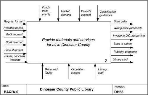
The IDEF0 model always starts with the presentation of the system as a whole - a single functional block with interface arcs extending beyond the considered area. Such a diagram with one functional block is called a context diagram, and is denoted by the identifier “A-0”.
The explanatory text for the context diagram must indicate the Purpose of building the diagram in the form of a brief description and fix the point of view (Viewpoint).
Determining and formalizing the goal of developing an IDEF0 - model is an extremely important point. In fact, the goal identifies the relevant areas in the system under study that should be focused on first. For example, if we model the activities of an enterprise in order to build an information system on the basis of this model in the future, then this model will differ significantly from the one that we would develop for the same enterprise, but with the aim of optimizing supply chains.
The point of view defines the main direction of development of the model and the level of detail required. A clear fixation of the point of view allows you to unload the model, refusing to detail and study individual elements that are not necessary, based on the chosen point of view on the system. For example, the functional models of the same enterprise from the point of view of the chief technologist and the financial director will differ significantly in the direction of their detailing. This is due to the fact that, in the end, the CFO is not interested in the aspects of processing raw materials on production machines, and the chief technologist does not need drawn schemes of financial flows. The correct choice of point of view significantly reduces the time spent on building the final model.
In the process of decomposition, the functional block, which in the context diagram displays the system as a whole, is drilled in another diagram. The resulting second-level diagram contains functional blocks that display the main subfunctions of the functional block of the context diagram and is called a Child diagram in relation to it (each of the functional blocks belonging to a child diagram is respectively called a Child Box). In turn, the parent function block is called the parent block in relation to the child diagram (Parent Box), and the diagram to which it belongs is called the parent diagram (Parent Diagram). Each of the sub-functions of the child diagram can be further detailed by a similar decomposition of the corresponding functional block. It is important to note that in each case of decomposition of a functional block, all interface arcs included in this block or outgoing from it are fixed in the child diagram. This achieves the structural integrity of the IDEF0 model. The decomposition principle is clearly shown in Figure 4. You should pay attention to the relationship between the numbering of functional blocks and diagrams - each block has its own unique serial number on the diagram (the number in the lower right corner of the rectangle), and the designation at the right angle indicates the number of the child diagram for this block ... The absence of this designation means that there is no decomposition for this block.
There are often cases when individual interface arcs do not make sense to continue to be considered in child diagrams below a certain level in the hierarchy, or vice versa - individual arcs have no practical meaning above a certain level. For example, it makes no sense to reflect the interface arc depicting a “detail” at the entrance to the function block “Turn on a lathe” on diagrams of higher levels - this will only overload the diagrams and make them difficult to understand. On the other hand, there is a need to get rid of separate “conceptual” interface arcs and not detail them deeper than a certain level. To solve such problems, the IDEF0 standard provides for the concept of tunneling. The Arrow Tunnel designation in the form of two parentheses around the beginning of the interface arc denotes that this arc was not inherited from the functional parent block and appeared (from the "tunnel") only in this diagram. In turn, the same designation around the end (arrow) of the interface arc in the immediate vicinity of the receiver block means the fact that this arc is displayed and will not be considered in the child diagram of this block. Most often it happens that individual objects and their corresponding interface arcs are not considered at some intermediate levels of the hierarchy - in this case, they are first “plunged into the tunnel” and then, if necessary, “returned from the tunnel”.
The final concept in IDEF0 is the Glossary. For each of the IDEF0 elements: diagrams, functional blocks, interface arcs, the existing standard implies the creation and maintenance of a set of relevant definitions, keywords, narratives, etc. that characterize the object displayed by this element. This set is called a glossary and is a description of the essence of this element. For example, for a control interface arc “payment order”, the glossary may contain a list of fields of the document corresponding to the arc, the required set of visas, etc. The glossary harmoniously complements the graphical language, providing the diagrams with the necessary additional information.

Figure 4. Decomposition of functional blocks.
The principles of limiting the complexity of IDEF0 diagrams
Typically, IDEF0 models carry complex and concentrated information, and in order to limit their congestion and make them readable, the corresponding complexity limits are adopted in the corresponding standard:
Limiting the number of functional blocks in the diagram to three to six. The upper limit (six) forces the designer to use hierarchies when describing complex items, and the lower limit (three) ensures that there is enough detail on the corresponding diagram to justify its creation;
Limiting the number of interface arcs suitable for one functional block (leaving one functional block) to four.
Of course, it is not at all necessary to strictly adhere to these restrictions, however, as experience shows, they are very practical in real work.
Discipline of group work on the development of the IDEF0-model
The IDEF0 standard contains a set of procedures that allow a large group of people from different areas of the modeled system to develop and agree on a model. Typically, the development process is iterative and consists of the following conditional stages:
Creation of a model by a group of specialists related to various areas of the enterprise. This group is called Authors in terms of IDEF0. Building an initial model is a dynamic process during which authors ask competent people about the structure of various processes. Based on the existing provisions, documents and survey results, a Model Draft of the model is created.
Distribution of the draft for review, approval and comments. At this stage, there is a discussion of the draft model with a wide range of competent persons (in terms of IDEF0-readers) in the enterprise. At the same time, each of the diagrams of the draft model is criticized and commented in writing, and then transferred to the author. The author, in turn, also agrees with the criticism in writing or rejects it outlining the logic of decision-making and returns the revised draft for further consideration. This cycle continues until the authors and readers come to a consensus.
Model approval. The approval of the agreed model occurs by the head of the working group in the event that the authors of the model and the readers do not have disagreements about its adequacy. The final model is a consistent view of the enterprise (system) from a given point of view and for a given purpose.
The visibility of the IDEF0 graphic language makes the model quite readable for persons who did not take part in the project of its creation, as well as effective for holding shows and presentations. In the future, on the basis of the constructed model, new projects can be organized aimed at making changes in the enterprise (in the system).
Features of the national practice of using functional modeling by means of IDEF0
In recent years, interest in the methodologies of the IDEF family has been steadily growing in Russia. I constantly observe this, looking at the statistics of calls to my personal web page (http://www.vernikov.ru), which briefly describes the basic principles of these standards. At the same time, I would call interest in such standards as IDEF3-5 theoretical, and in IDEF0 quite practically justified. As a matter of fact, the first Case-tools allowing to build DFD and IDEF0 diagrams appeared on the Russian market back in 1996, simultaneously with the release of the popular book on the principles of modeling in the SADT standards.
Nevertheless, most executives still regard the practical application of modeling in IDEF standards as a fashion statement rather than an effective way to optimize the existing business management system. Most likely this is due to a pronounced lack of information on the practical application of these methodologies and with the indispensable software bias of the vast majority of publications.
It is no secret that almost all projects for the survey and analysis of the financial and economic activities of enterprises now in Russia are in one way or another connected with the construction of automated control systems. Thanks to this, the IDEF standards, in the understanding of the majority, have become conditionally inseparable from the implementation of information technologies, although with their help it is sometimes possible to effectively solve even small local problems, literally with the help of a pencil and paper.
When conducting complex enterprise survey projects, the development of models in the IDEF0 standard allows you to visually and effectively display the entire mechanism of enterprise activity in the desired context. Most important, however, is the collaboration that IDEF0 provides. In my practice, there were quite a few cases when the construction of the model was carried out with the direct help of employees of various departments. At the same time, the consultant explained to them the basic principles of IDEF0 in a fairly short time and taught them to work with the corresponding application software. As a result, employees of various departments created IDEF diagrams of the activities of their functional unit, which were to answer the following questions:
What goes to the unit “at the entrance”?
What functions, and in what sequence, are performed within the unit?
Who is responsible for each of the functions?
What is the executor guided by when performing each of the functions?
What is the result of the unit's work (output)?
After agreeing on draft diagrams within each specific department, they are assembled by the consultant into a draft enterprise model, in which all input and output elements are linked. At this stage, all discrepancies of individual diagrams and their controversial places are recorded. Further, this model again passes through the functional departments for further agreement and making the necessary adjustments. As a result, in a fairly short time and with the involvement of a minimum of human resources from a consulting company (and these resources, as you know, are very expensive), an IDEF0-model of an enterprise is obtained according to the “As is” principle, and, which is important, it represents an enterprise with positions of employees who work in it and thoroughly know all the nuances, including informal ones. In the future, this model will be transferred for analysis and processing to business analysts who will look for bottlenecks in company management and optimize key processes, transforming the “As is” model into the corresponding “As should be” view. Based on these changes, a final conclusion is made, which contains recommendations for reorganizing the management system.
Of course, such an approach requires a number of organizational measures, primarily on the part of the management of the surveyed enterprise. This is due to the fact that this technique implies the assignment of additional responsibilities to some staff in the mastery and practical application of new methodologies. However, in the end, this pays off, since the additional one or two hours of work of individual employees over several days can significantly save money on the payment of consulting services to a third-party company (which in any case will tear away from the work of the same employees with questionnaires and questions). As for the employees of the enterprise themselves, in one way or another, I have not met any expressed opposition on their part.
The conclusion from all this can be done as follows: it is not at all necessary to come up with solutions for standard problems every time. Whenever you are faced with the need to analyze a particular functional system (from the spacecraft design system to the process of preparing a complex dinner), use the methods that have been tried and tested over the years. One of these methods is IDEF0, which allows you to solve complex life problems with the help of its simple and understandable tools.
It might be useful to read:
- Craft from plasticine for the day of cosmonautics;
- School riddles - fun activity for kids;
- How to mold a plasticine bat step by step with a photo;
- Embroidered keyrings Embroidered keychain scheme;
- Station game "fair";
- Games in the summer day camp for primary school children;
- Camp competitions for children;
- Children's riddles about transport;